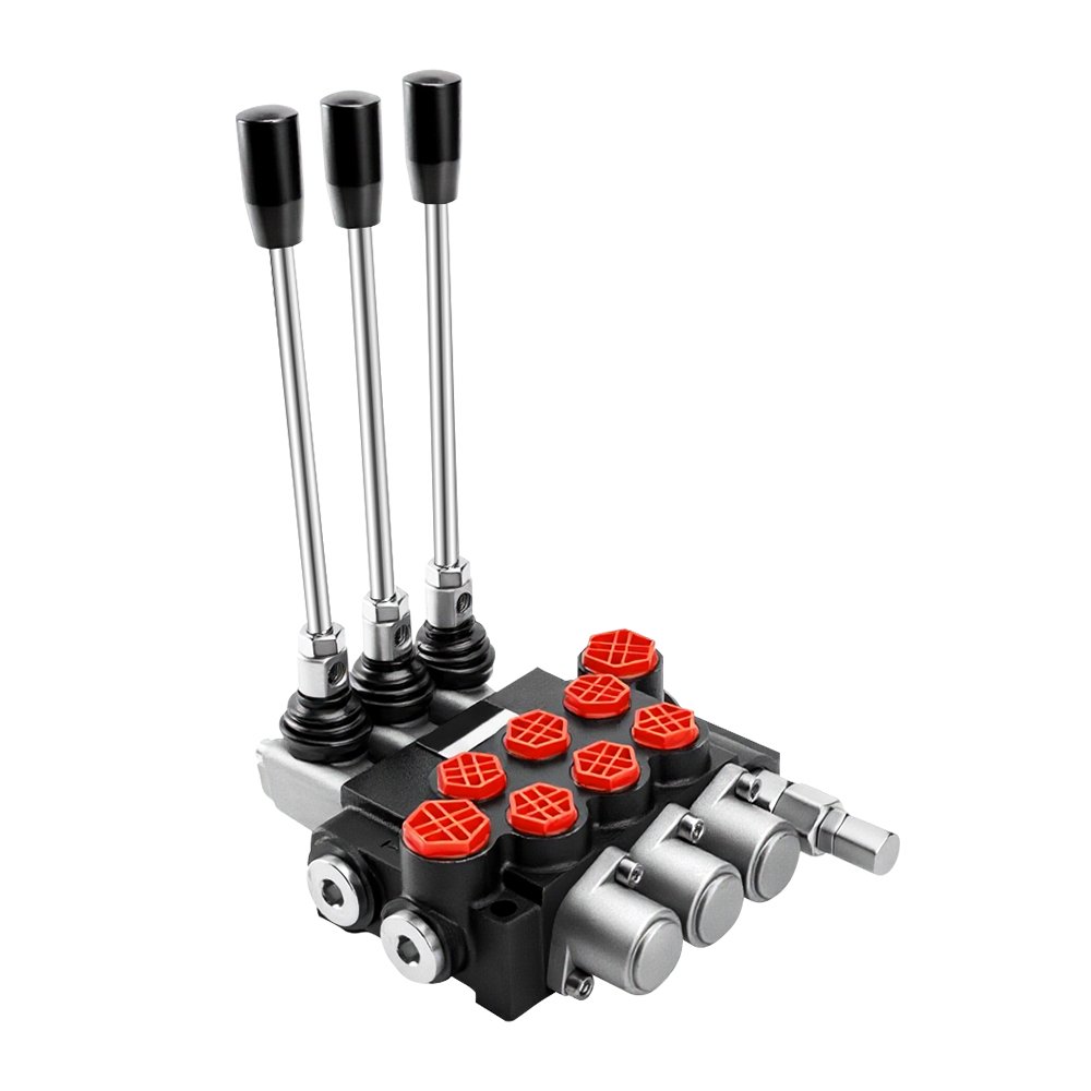
Integrating a hydraulic control valve into an existing hydraulic system requires careful attention to compatibility, installation, and operating conditions. A valve may meet its basic pressure and flow requirements yet still cause problems if its connections, control method, or physical dimensions do not match the rest of the system.
A customized hydraulic control valve can be configured around specific equipment requirements, making system integration more adaptable when standard valve dimensions or functions are unsuitable. However, successful integration still depends on accurate specifications and proper installation procedures.
Review the Existing Hydraulic Circuit
Start by examining the complete hydraulic circuit before installing the valve. Identify the pump, reservoir, actuators, filters, hoses, existing valves, and control components connected to the circuit.
The hydraulic schematic is particularly useful for understanding fluid paths and determining where the new valve should be installed. It can also help identify potential pressure or flow restrictions.
Confirm Valve Compatibility
The valve should be checked against the system’s operating requirements before installation. Important parameters include:
- Maximum and normal operating pressure
- Continuous and peak flow rate
- Hydraulic fluid type
- Operating temperature
- Valve function
- Actuation method
- Port and connection specifications
- Mounting dimensions
Comparing these details with the existing system can help identify compatibility issues early.
Check Port and Connection Requirements
Hydraulic connections must match correctly to prevent leakage and installation problems. Confirm port sizes, thread types, connection standards, and port locations before connecting the valve.
For replacement projects, dimensional drawings can be especially useful. Even small differences in port orientation or mounting position can make installation difficult in a confined machine compartment.
Evaluate Installation Space
Measure the available space around the installation point before mounting the valve. Consider not only the valve’s overall dimensions but also the space required for hoses, electrical connections, adjustment, inspection, and future maintenance.
A compact installation should still allow technicians sufficient access to service the component without removing unrelated equipment.
Prepare the Hydraulic System
Before installation, the hydraulic system should be prepared according to the equipment manufacturer’s procedures. The system should be depressurized, and appropriate measures should be taken to prevent contamination from entering open hydraulic connections.
Cleanliness is important because dirt and particles can interfere with precision valve components. All exposed ports and lines should be protected during installation.
Install the Valve Correctly
Follow the approved installation drawing and mounting specifications. The valve should be positioned correctly and securely fastened using appropriate hardware and procedures.
Avoid forcing connections into alignment. If ports or mounting points do not line up, the issue should be investigated rather than corrected through excessive mechanical force.
Connect Hydraulic Lines Carefully
Hydraulic hoses and tubing should be routed to avoid excessive bending, twisting, vibration, or contact with sharp edges. Proper routing can reduce mechanical stress on both the lines and valve connections.
Connections should be tightened according to the applicable specifications. Over-tightening can damage threads or components, while insufficient tightening may result in leakage.
Connect the Control System
If the valve uses electrical or electronic actuation, verify the required voltage, connector type, wiring arrangement, and control signal before energizing the system.
For proportional or electronically controlled valves, the control parameters should also be compatible with the machine’s controller. Incorrect electrical settings can affect valve response or prevent proper operation.
Verify Pressure and Flow Settings
Once the valve is installed, confirm that pressure and flow settings correspond to the intended hydraulic circuit. Adjustments should be made carefully and according to the approved system requirements.
Do not assume that settings from a previous valve will automatically apply to the new configuration. Differences in valve design can affect pressure drop, flow characteristics, and actuator behavior.
Check for Leakage
Before placing the equipment under full operating load, inspect hydraulic connections and the valve body for signs of leakage.
If leakage is detected, depressurize the system before attempting to correct the connection. Hydraulic systems can operate at high pressure, so inspection and maintenance should follow appropriate safety procedures.
Test the System Gradually
Initial testing should be performed under controlled conditions. Start with suitable low-load or low-risk operating conditions where possible and observe valve response, actuator movement, pressure behavior, and flow.
Gradually move toward normal operating conditions while monitoring the system. This approach can make it easier to identify unexpected behavior before the equipment reaches full load.
Monitor System Performance
After installation, monitor the hydraulic system for changes in performance. Useful indicators include:
- Pressure stability
- Actuator speed
- Response time
- Fluid temperature
- Leakage
- Unusual noise or vibration
- Pressure drop
- Control consistency
Comparing these observations with the expected operating specifications can help confirm whether the integration was successful.
Consider Filtration and Fluid Cleanliness
The condition of the hydraulic fluid can directly affect valve performance. Contamination may cause sticking, wear, leakage, or inconsistent control behavior.
Check that the system’s filtration arrangements are appropriate and that hydraulic fluid is maintained according to the equipment requirements. Clean installation practices are equally important.
Document the Installation
Keep records of the valve specifications, installation date, connection configuration, pressure settings, control parameters, and test results.
Good documentation can simplify future maintenance and troubleshooting. It also provides a useful reference if the hydraulic circuit is modified later.
Plan for Maintenance
Integration should take future service requirements into account. Ensure that technicians can access adjustment points, connections, seals, and other serviceable components.
Regular inspection can help identify leakage, contamination, abnormal temperature, or changes in actuator performance before they develop into larger system problems.
Troubleshoot Common Integration Issues
If the system does not perform as expected after installation, review the basic installation and specification points first. Common causes can include incorrect connections, unsuitable pressure settings, inadequate flow capacity, electrical control problems, trapped air, or contamination.
Comparing actual system behavior with the original hydraulic schematic and valve specifications can help narrow down the source of the problem.
Final Considerations
Integrating a customized hydraulic valve successfully requires more than physically installing the component. The valve must be compatible with the hydraulic circuit, connections, control system, installation environment, and operating conditions.
A systematic approach—from reviewing the circuit and checking specifications to installing, testing, and monitoring the valve—can reduce integration problems. Proper documentation and ongoing maintenance can then help support reliable performance throughout the valve’s service life.